Brownville, Maine

General Introduction
The Town of Brownville Wastewater Treatment Plant
consists of primary settling followed by subsurface
disposal of primary effluent and is designed for the
removal of raw BOD and Suspended Solids at
concentrations of 250 mg/l and 200 mg/l respectively, in
the influent and at an average daily flow of 0.065 MGD.
Peak capacity of the plant is 0.33 MGD.
System Description
The
Town’s wastewater treatment plant consists of influent
flow metering, primary settling and disposal of primary
effluent in infiltration beds. Treatment of primary
effluent in filtration beds results from the growth of
microorganisms in the filtration media which consume
organic waste, thereby removing biochemical oxygen
demand and suspended solids. The effluent is also
treated by absorption, adsorption, and filtration.
Filtered effluent is discharged to the groundwater and
enters the pleasant River via subsurface flow or is
intercepted and collected by the underdrain system.
Underdrain flow is discharged to the Pleasant River, a
Class C waterway.
Influent wastewater flow to the treatment facility from
Pump Station #1 is measured, indicated, recorded and
totalized at the control panel in the operations
building. The influent flow-metering manhole is a 6-foot
diameter manhole. A 3-inch magnetic flow meter, a local
flow indicator and transmitter are located in the
manhole.
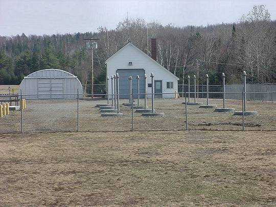
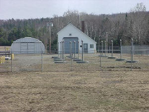
Primary Settling Tanks
Influent
flow from Pump Station #1 ( Main Pump Station ) via a 6
inch force main is discharged to a flow distribution
chamber at the treatment facility. Flow distribution is
achieved with 60-degree V-notch slide gates (four) which
allow flow to be equally divided and directed to any one
or more of the four primary settling tanks. Normal
operation is to have 25% of the flow going to each one
of the settling tanks. Each settling tank has a surface
area of 224 square feet and a working depth of 9 feet, 9
inches. Volume of each tank is therefore 16,336 gallons.
Primary settling tanks are provided with the following:
a. Influent Pipe
b. Adjustable weir plate and effluent trough
c. Scum and influent flow control baffles
d. Vent pipe
e. Access manholes and ladders.
Dosing Chambers
Effluent from the
four primary settling tanks is discharged to 2 dosing
chambers. Each dosing chamber is provided with 3
submersible pumps for pumping primary effluent to the
infiltration beds. Each pump discharge line is provided
with a check, gate and plug valve. The discharge pipe
manifold is piped and valved to allow any one of the
three dosing pumps to serve any one of the three sets of
infiltration beds. Level controls are provided for
starting and stopping pumps, high and low level alarms.
A pressure sensor is located immediately downstream from
each discharge valve. The purpose of the pressure sensor
is to detect a high pressure in the discharge line (due
to a blockage), shut down the pump and signal a high
discharge pressure alarm back to the operations
building.
Flow
Diversion Manholes
Each dosing pump’s discharge main passes through a flow
diversion manhole. Each pair of infiltration beds are
served by one dosing pump and one flow diversion
manhole. It is piped and valved to allow flow to be
applied to either infiltration bed by manual selection.
Infiltration Beds
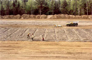 |
|
Infiltration
Beds during Construction Phase
|
The primary settling tank effluent is applied to the
infiltration beds by the dosing pumps. Infiltration beds
are provided in 6 sets of 2 each and are numbered as 1A
through 6A and 1B through 6B. This enables the operator
to stop flow to each bed by rotation thereby allowing
the infiltration bed time to rest and rejuvenate. Each
infiltration bed has overall dimensions of 54’ 6” by
400’ long giving each an area of 21,800 sq. ft.. Each
infiltration bed is divided into four 100’ long cells.
Distribution of the flow is as follows:
a. Each dosing pump has a 6-inch discharge main piped to
an infiltration bed flow diversion manhole. Valving in
the diversion manholes allows flow application to
infiltration bed series A or series B
b. The 6-inch mains from the flow diversion manhole
feeds a 4” distribution header which runs along the
centerline for the entire 400 foot length of the
infiltration bed.
c. The 4 inch distribution header feeds 1 ½”
distribution laterals located at 10 foot intervals along
the length of each infiltration cell. These laterals
have 3/8” diameter holes spaced at 9’ 1” intervals for
application of primary effluent to the beds.
The effluent from the infiltration beds is discharged to
the groundwater. An underdrain system conveys
groundwater to an effluent metering manhole and chlorine
contact tank prior to discharge to the Pleasant River.
Flow Pattern
The treatment system is designed to allow two equipment
systems to be operated in parallel.
In the usual configuration, wastewater enters the system
at the flow distribution chamber and is equally split
between the primary settling tanks. Primary effluent is
pumped to the infiltration tanks.
Effluent Flow Metering
Effluent from the infiltration beds is measured through
a 2” parshall flume. Flow data is transmitted to a
recorder and totalizer installed in the operations
building.
Outfall
Final effluent from the unused chlorine contact tank is
discharged to the Pleasant River through an 8-inch
diameter outfall pipe. The outfall pipe is installed
under the riverbed and 2 flared pipes are elevated above
the riverbed for flow diffusion.
Sludge Storage and Disposal
A prefabricated 16,000-gallon concrete septic tank is
provided for sludge storage. Sludge from the primary
settling tanks will be transferred to the sludge storage
tank with a portable pump when the depth reached 3 feet.
Sludge from the storage tank is transported by pumper
truck to the dedicated land application site adjacent to
the treatment facility.
Emergency Power
Emergency power and automatic transfer of such takes
place in the operations building via a permanently
mounted emergency standby generator which is located in
the rear of the building.
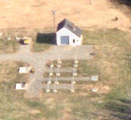
Aerial View of the
Operations Building
just after substantial completion.
|